
CuteBoard - Making a custom mechanical keyboard from scratch
I like a good click-clacking keyboard. It's not that I can't stand the contemporary membrane ones - some of them are fine, and most serve their purpose of being cheap, readily available input devices - but as someone who spends long hours in front of a computer screen every day, I simply strive for better.
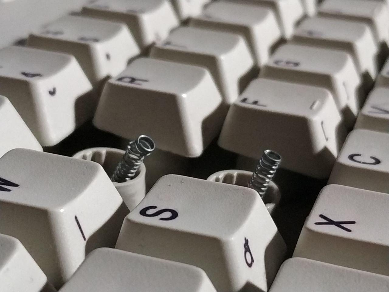
Just a month ago, my daily driver was an IBM Model M2 - a cheaper, younger "Model M" than the original Model M. It had some remarkable features, one of them was being a full-fledged buckling spring keyboard, while looking like a smaller, ordinary membrane one. Unfortunately, being the cheaper option, some of the springs started wearing off - after all, the keyboard has been kicking around for over 25 years.
 ouch ouch ouch ouch ouch
While trying to move the worn off spring to a key that I use less than `E`, I stumbled upon a build quirk I've already encountered during previous disassemblies...
ouch ouch ouch ouch ouch
While trying to move the worn off spring to a key that I use less than `E`, I stumbled upon a build quirk I've already encountered during previous disassemblies...
 "I fscked up the disassembly, again"
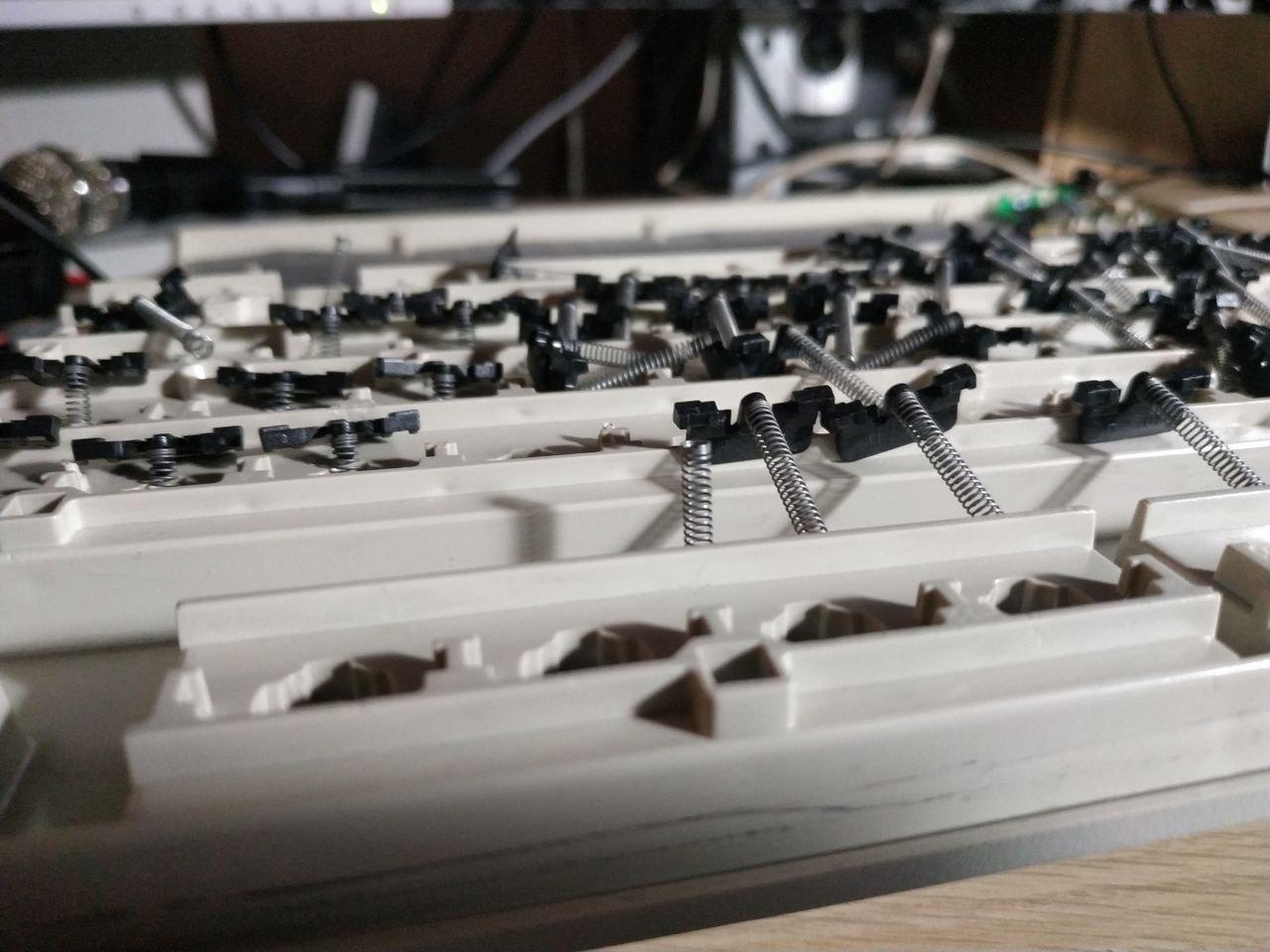
See, there's no good way to actually handle these keyboards. So far, I've opened mine at least 5 times, of which only once did I do it correctly. Not a great success ratio for something that takes literal hours to reassemble if you do it wrong.
"I fscked up the disassembly, again"
See, there's no good way to actually handle these keyboards. So far, I've opened mine at least 5 times, of which only once did I do it correctly. Not a great success ratio for something that takes literal hours to reassemble if you do it wrong.
I'm having none of this.
After I managed to reassemble this mess, I discovered that the situation is only just slightly better. See, this keyboard has other cost-cutting measures built-in, such as.. plastic stabilizers. Those can - and will - snap.
I was done with it.
I embarked on a journey to find an acceptable mechanical keyboard that I could call my own. Something small, with good keyfeel, and it had to be tactile, yet preferably not too loud. For over a week I've read about everything from switch types, through keycap profiles, ending on different custom boards. But then it turned out that my budget wasn't as high as I expected it to be (those things tend to get expensive). To get what I desired, I'd have to save up and wait a few months. Unless I could cheap out...
Building my own, on the cheap
I had the following principles in mind when I started working on this project:
- Utilize materials that I already have at home. Possibly spend no extra money.
- Single keys only, because:
- stabilizers are a hit or miss, and you never ever miss huh
- it's just simpler to design a board around multiple same sized keys
- The board has to be as small as possible. Around 60-65% would be the best.
Getting the base parts
The first order of business was to acquire the parts. I've had a Chicony KB-5191 laying around, and it wasn't in the greatest condition. I don't believe in preservation of hardware that's not significant in terms of rarity or sentimental value, so I disassembled the keyboard and desoldered most of the switches. According to deskthority, KB-5191 housed a lot of different switches and mount configurations - mine had the Futaba Clicky Cherry MX mount switches, mounted on a bog standard double sided PCB. Those are not ideal, but I didn't want to spend 130PLN (~30USD) just to get some Gateron Blues/Browns.
Early attempts
"You see that 3D Printer sitting on the desk behind you? Me neither."
 So, my next logical step was to drill 210 holes into the back of a X200 screen case
 ... and then, install the switches
I originally chose this approach because I was looking for something sturdy that could act as a nice backplate. This was an obvious fit, as it was already damaged prior to me receiving it, and the flex was minimal - even compared to the original PCB. This was ideal right up until the moment when I tried to connect the switches into a matrix - I forgot that ThinkPad cases are famously a magnesium alloy, and like most alloys, this one is a good conductor. I may have facepalmed when I realized.
... and then, install the switches
I originally chose this approach because I was looking for something sturdy that could act as a nice backplate. This was an obvious fit, as it was already damaged prior to me receiving it, and the flex was minimal - even compared to the original PCB. This was ideal right up until the moment when I tried to connect the switches into a matrix - I forgot that ThinkPad cases are famously a magnesium alloy, and like most alloys, this one is a good conductor. I may have facepalmed when I realized.
Back to the drawing board
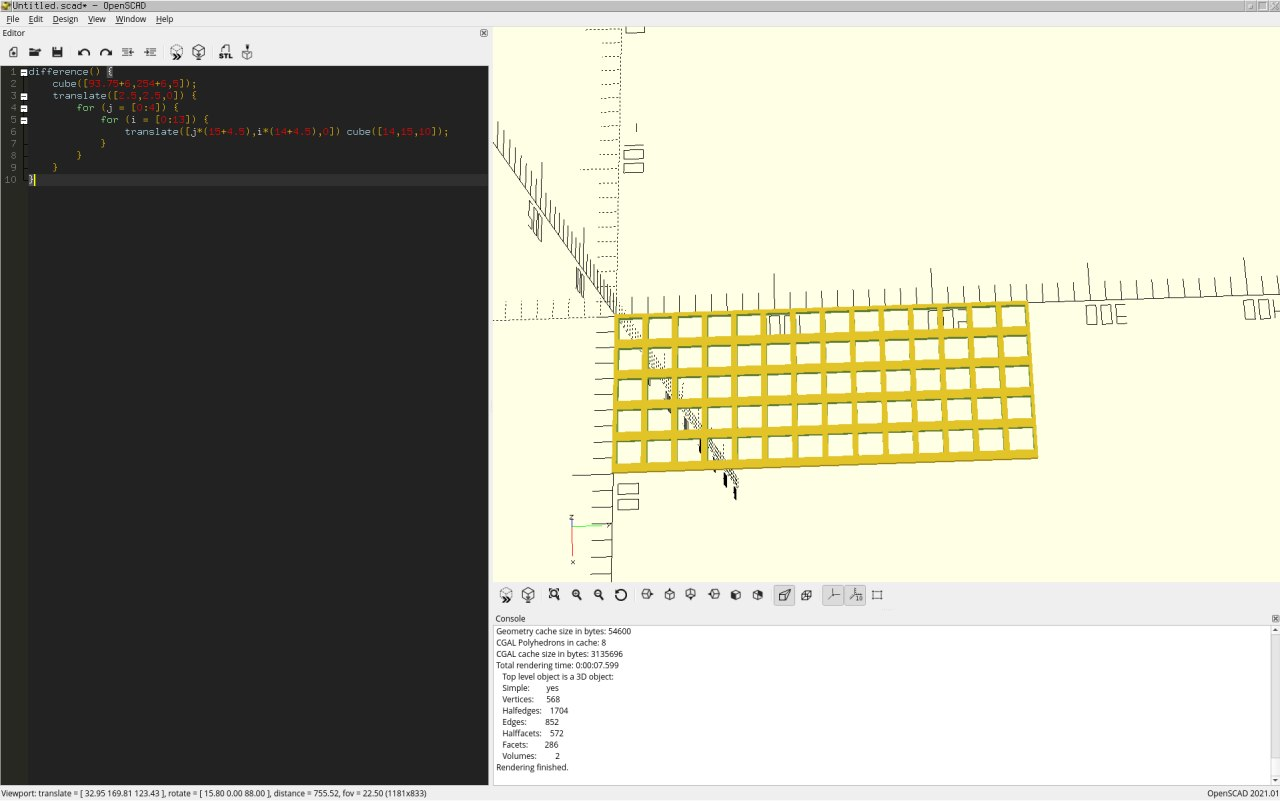
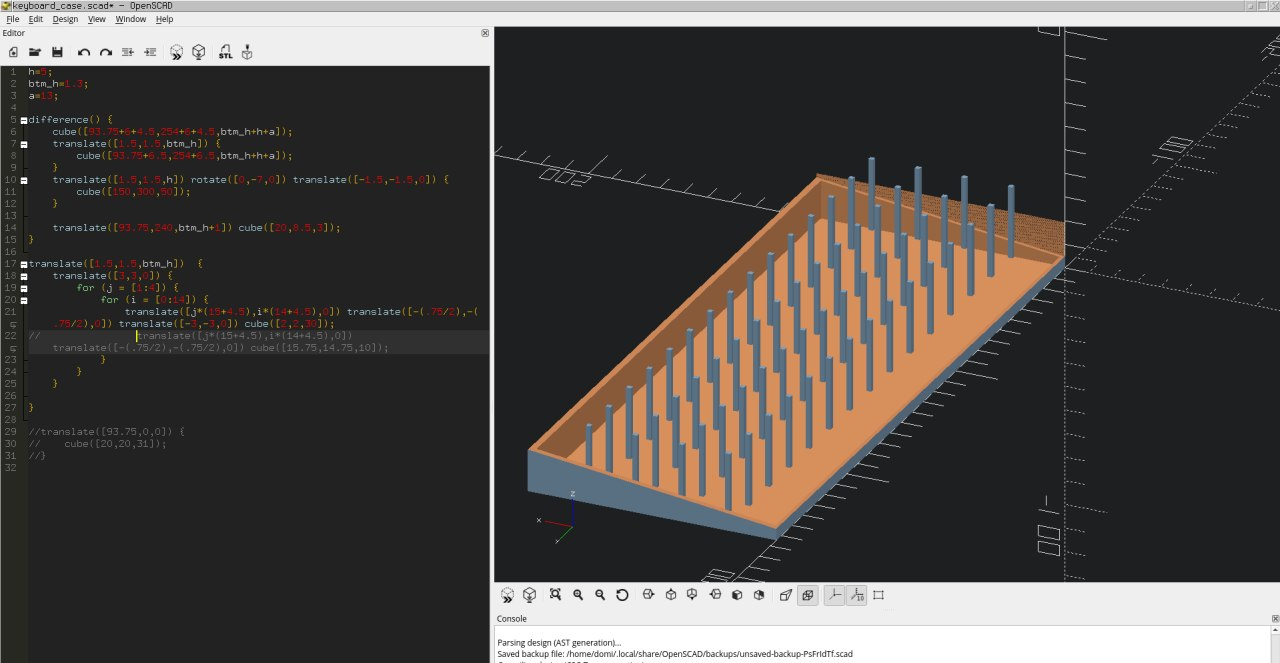
 OpenSCAD model of the plate I made, later cut in Slic3r
I made precise measurements of the switch dimensions (remember, Futaba MA are "cherry mx compatible" only in terms of the keycap mount), and I quickly scribbled up a holder plate in OpenSCAD. After dividing it into two parts, I printed the smaller one first to make sure I didn't make any huge mistakes:
OpenSCAD model of the plate I made, later cut in Slic3r
I made precise measurements of the switch dimensions (remember, Futaba MA are "cherry mx compatible" only in terms of the keycap mount), and I quickly scribbled up a holder plate in OpenSCAD. After dividing it into two parts, I printed the smaller one first to make sure I didn't make any huge mistakes:
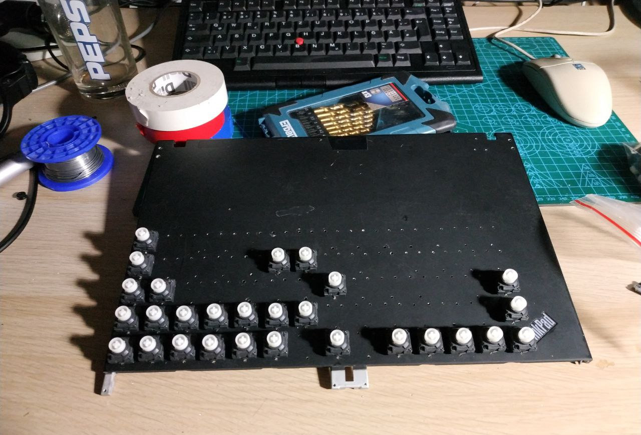
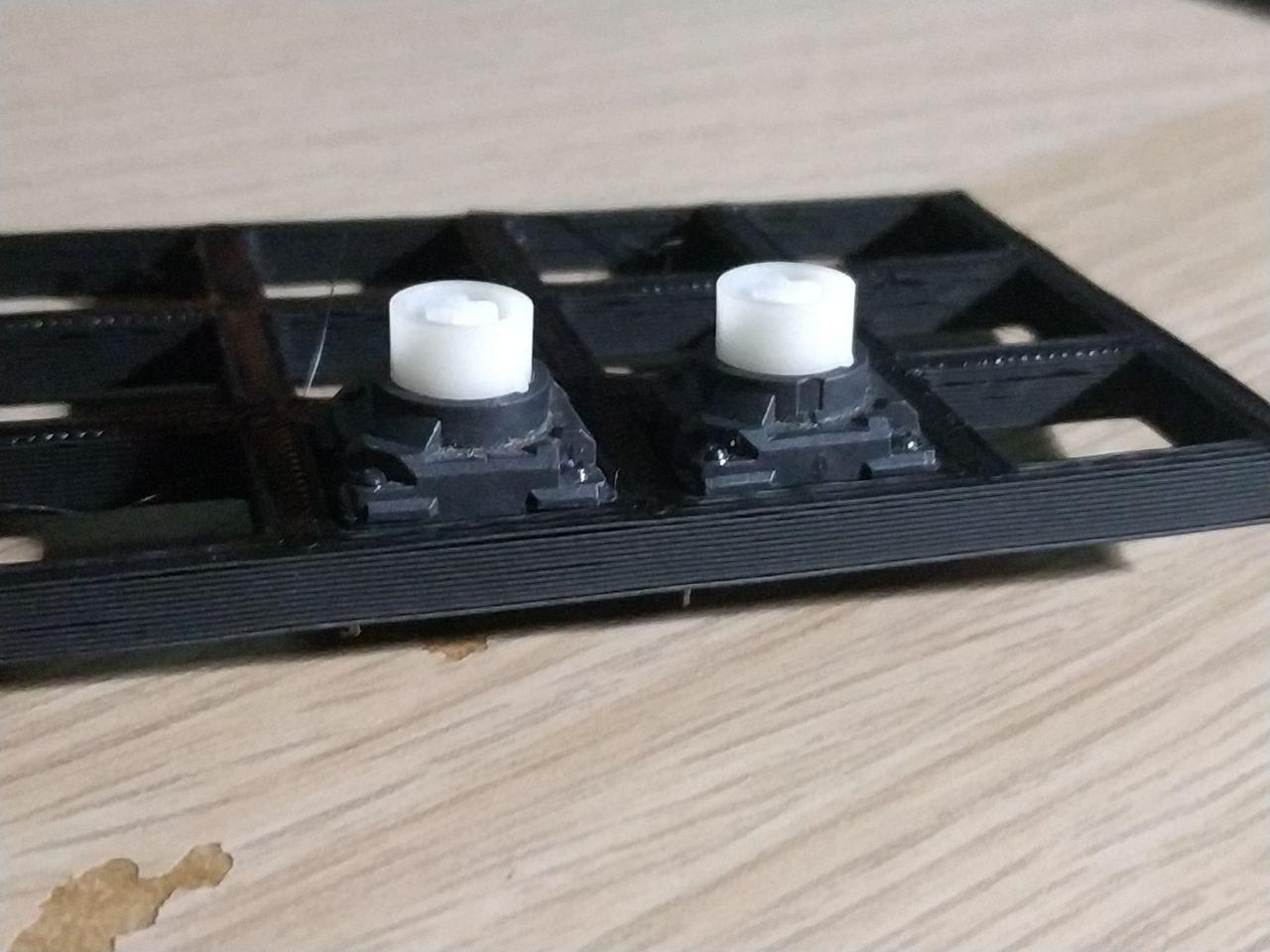 The plate, printed
This was really as close to perfection as I could've hoped for. In retrospect, I could have made the holes a bit smaller, so the switches would fit in a bit tighter, but it doesn't affect the usability in any way.
Joining parts of the plate together wasn't an easy enndeavour either - at first, I tried acetone, but the join wasn't strong enough to sustain the stress of me assembling the keyboard. Out of options and desperate for answers, I joined the two parts by melting edges of the prints while they were close-by together. This, unfortunately, pushed the column be a tiny bit further from the rest, but it's barely noticeable visually, and I don't really notice it when typing.
The Matrix
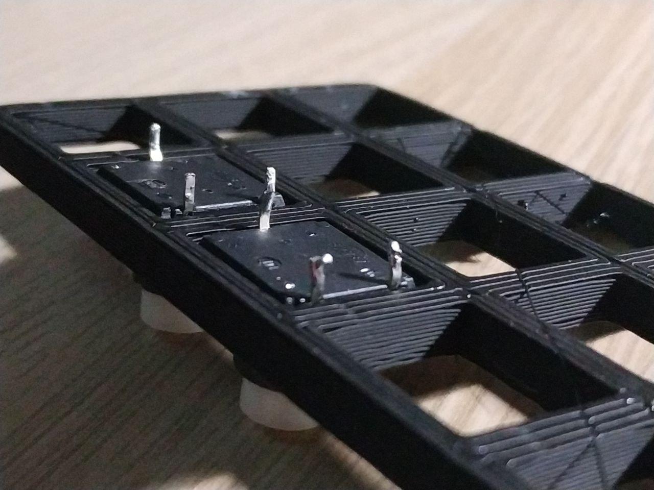
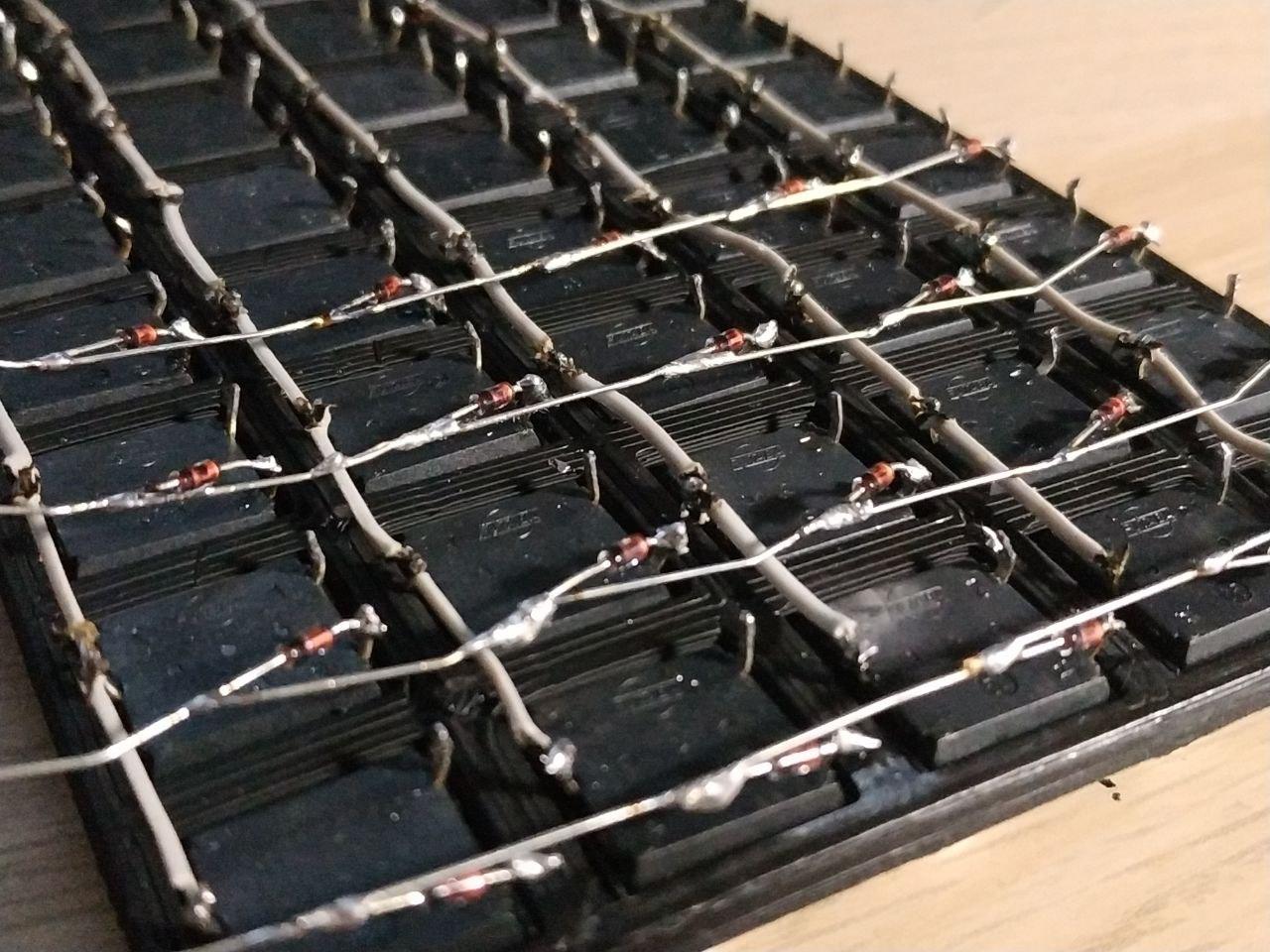
To cut costs, this design is completely PCB-less (well, except the board with the µC). I've carefully soldered wires to rows, diodes to columns, and used a neat trick to make it a bit tidier - the columns are made up of diodes soldered together, without any sort of extra cable.
 starting to solder the parts
If you're interested in the details of how a keyboard matrix works, why I used diodes next to every switch and more, check out this helpful blogpost.
starting to solder the parts
If you're interested in the details of how a keyboard matrix works, why I used diodes next to every switch and more, check out this helpful blogpost.
The case
 Spiky boii
Designing the case was mostly a case of me measuring my current keyboard, and doing some modifications so it would be kept a bit smaller. Finally, I came up with this:
Spiky boii
Designing the case was mostly a case of me measuring my current keyboard, and doing some modifications so it would be kept a bit smaller. Finally, I came up with this:
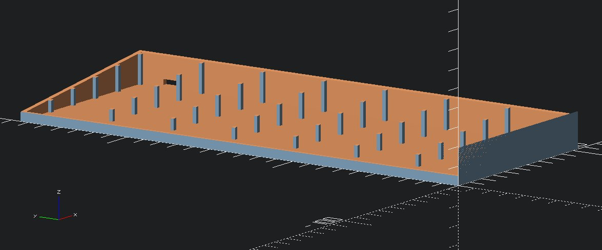 Less spiky boii
The spike-like structures are there to reduce the board flex, and they’re positioned right below the joints of the plate. The plate itself fits right into the case, leaving a few milimiters below it to allow for cable management and, well, for the matrix to fit.
Less spiky boii
The spike-like structures are there to reduce the board flex, and they’re positioned right below the joints of the plate. The plate itself fits right into the case, leaving a few milimiters below it to allow for cable management and, well, for the matrix to fit.
The design is available in the project repository ^w^
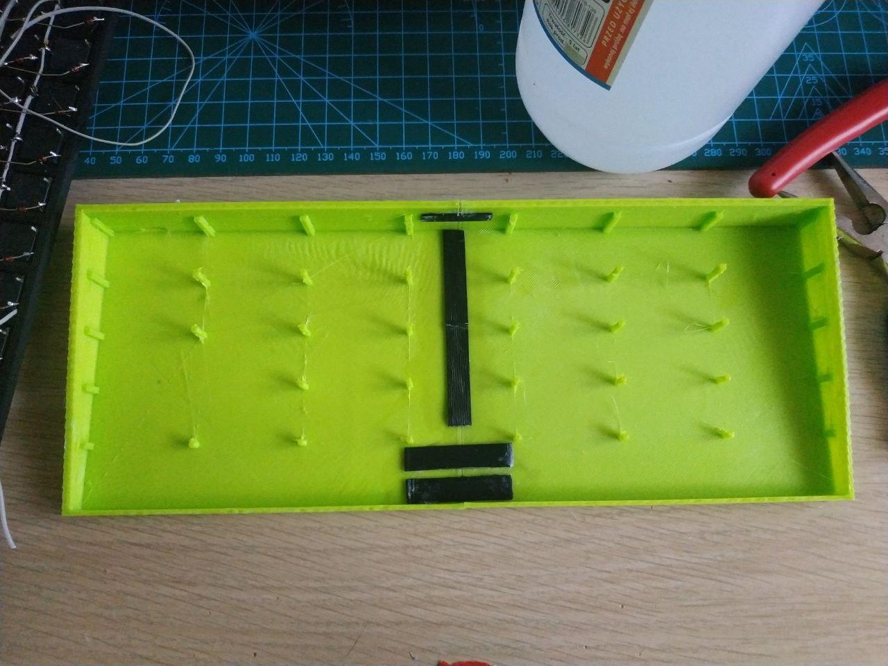 two printed parts connected together
After printing the case as two separate parts, I again used some acetone to fix them in place. For extra stability, some flat print scraps were used as joiners, and so far it's been holding up perfectly well. I didn't want to melt the plastic like in the case of the plate, because it's a part exposed to the end-user, and I'd prefer for it to look nice and clean.
two printed parts connected together
After printing the case as two separate parts, I again used some acetone to fix them in place. For extra stability, some flat print scraps were used as joiners, and so far it's been holding up perfectly well. I didn't want to melt the plastic like in the case of the plate, because it's a part exposed to the end-user, and I'd prefer for it to look nice and clean.
Assembly
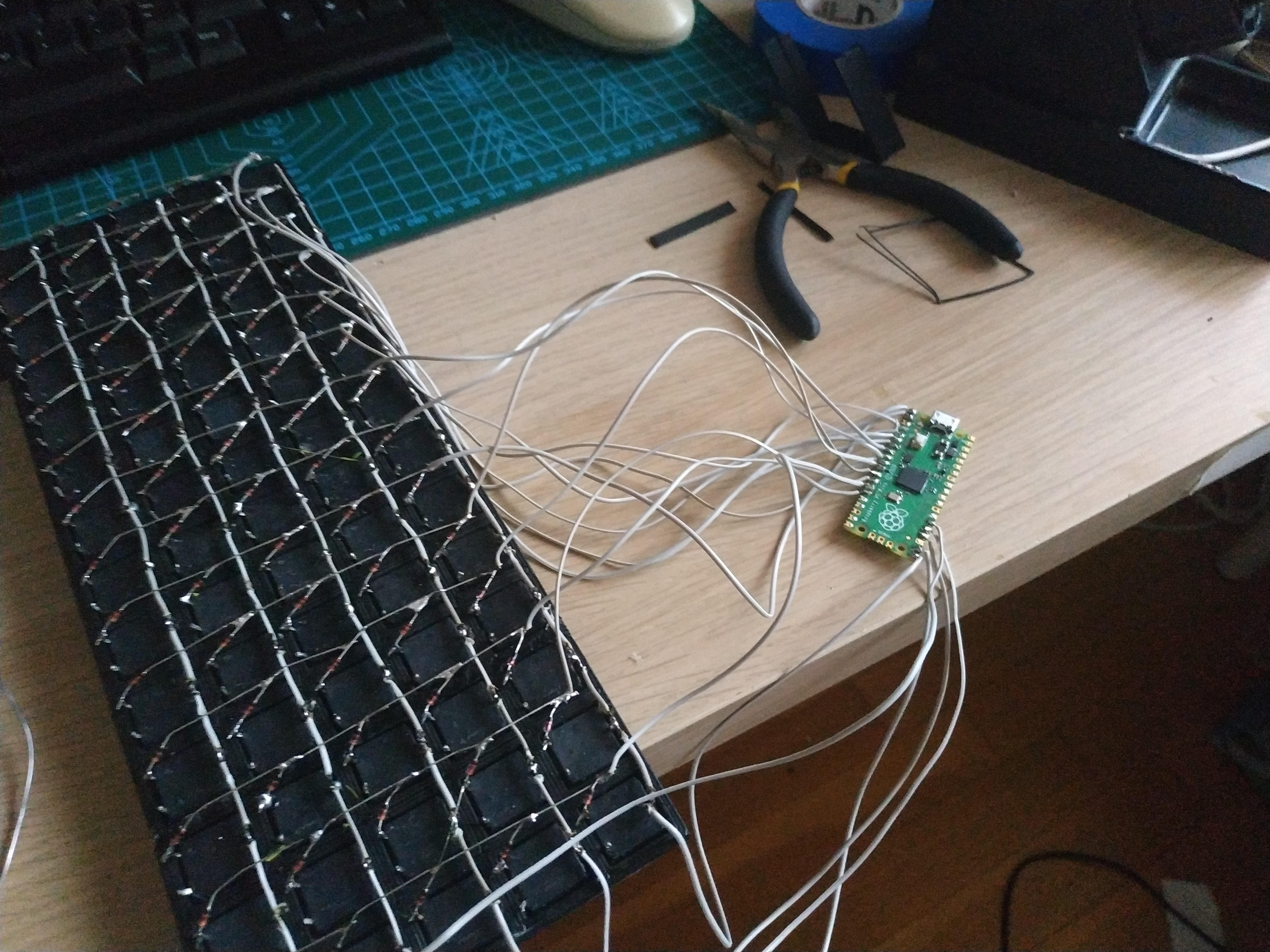 the whole jig attached to a pi pico
After gluing the pico to the bottom of the case (I unfortunately did not think about a better mounting mechanism), it was a matter of making sure that the cables don't get stuck up against the vertical support columns. Surprisingly, that wasn't as hard as I initially imagined.
the whole jig attached to a pi pico
After gluing the pico to the bottom of the case (I unfortunately did not think about a better mounting mechanism), it was a matter of making sure that the cables don't get stuck up against the vertical support columns. Surprisingly, that wasn't as hard as I initially imagined.
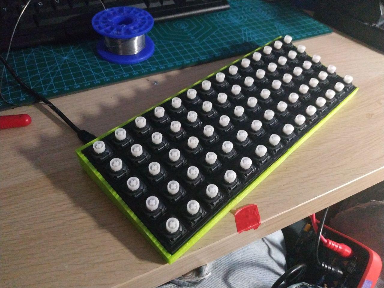 the assembled keyboard, w/o keycaps
After putting the parts together, I used even more acetone to join the plate and the case. This is something I wish I'd done differently, because disassembly is way harder, and potentially more destructive. Future designs should use screws or latches.
the assembled keyboard, w/o keycaps
After putting the parts together, I used even more acetone to join the plate and the case. This is something I wish I'd done differently, because disassembly is way harder, and potentially more destructive. Future designs should use screws or latches.
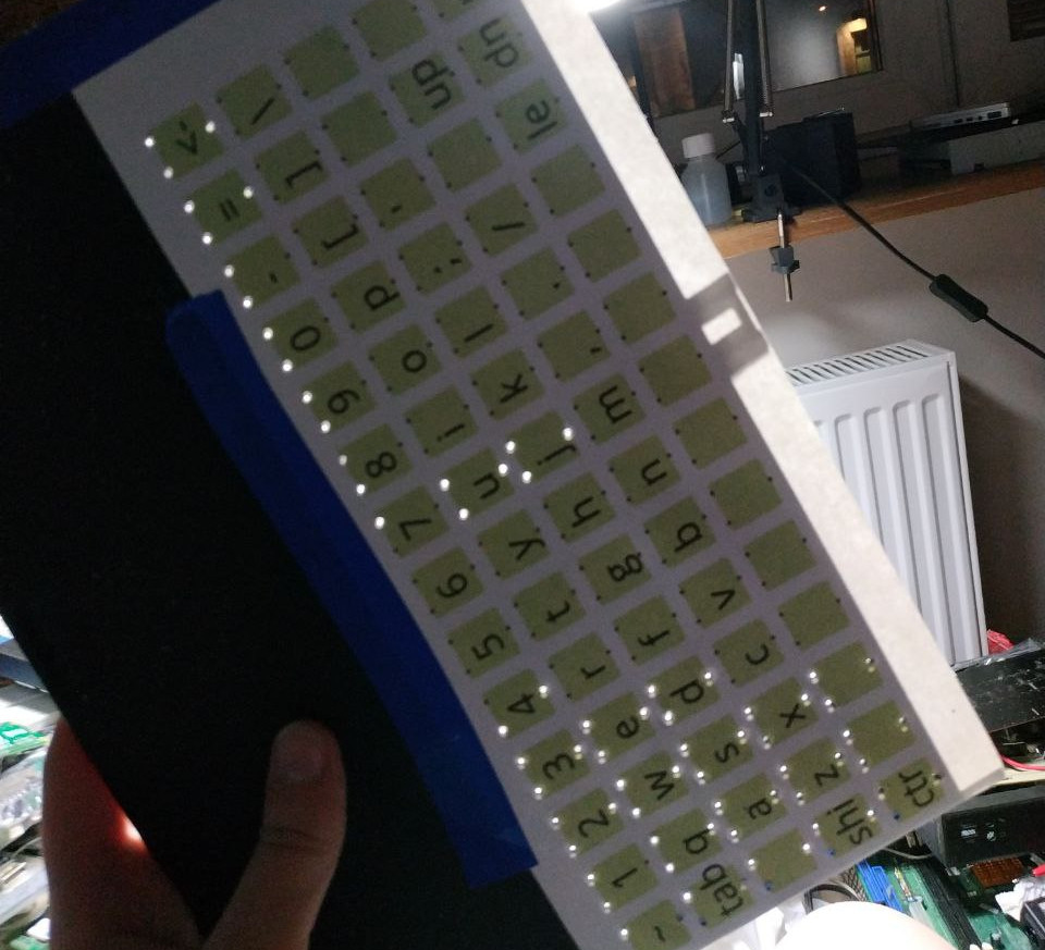
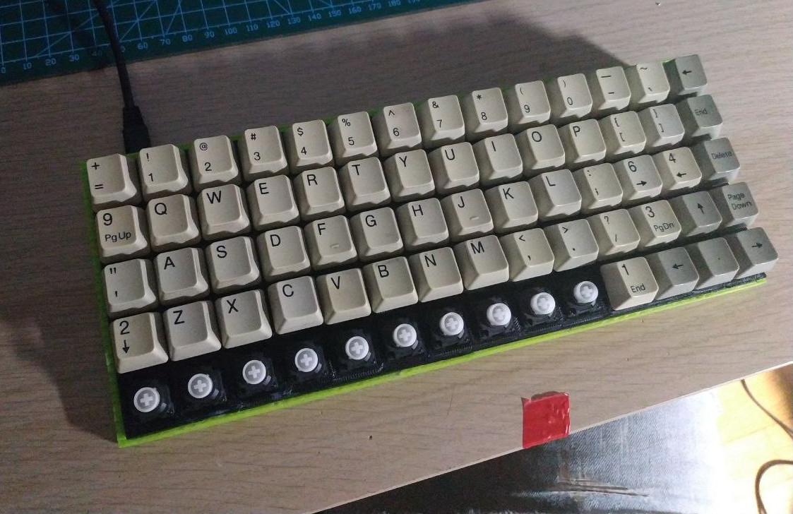 keyboard with most of the original keycaps on
For keycaps, I rescued some of the 1x ones from the donator Chicony board. Problem being, that there weren't enough of those for all of the rows...
keyboard with most of the original keycaps on
For keycaps, I rescued some of the 1x ones from the donator Chicony board. Problem being, that there weren't enough of those for all of the rows...
3D printing keycaps
"If you can print a keyboard, you surely can print the keycaps too?"
This has turned out to be one of the hardest parts of the whole build. The keycap is the part you actually touch the most, so it's way less forgiving than printing the case or any other part of the build. The keycaps have to be flat and as polished as possible - having sharp edges or rough surface makes it way less satisfying to write on.
I've used the keyv2 OpenSCAD library for generating keycaps parametrically, and it saved me a ton of R&D trouble. Thanks to this library, all I needed to do to generate a set of keys was to import the library, and choose the key profile.
My overall results from printing Cherry profile keycaps are as follows:
 nicely printed keycaps on layer height=~0.1mm (left), quickly printed keycaps on layer height=0.5mm (right)
The keycaps are quite likely the only part I'd like to change about this build. I'd prefer a set of blank keycaps in a variety of colours from.. green to green. Maybe some black ones for special purpose keys.
nicely printed keycaps on layer height=~0.1mm (left), quickly printed keycaps on layer height=0.5mm (right)
The keycaps are quite likely the only part I'd like to change about this build. I'd prefer a set of blank keycaps in a variety of colours from.. green to green. Maybe some black ones for special purpose keys. If you'd like to make this happen, I have a ko-fi..
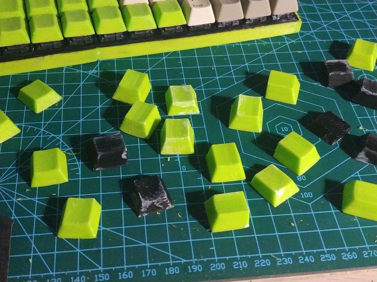 trying to treat the polished keycaps with acetone
To make the surface and the edges less rough, I tried polishing them with sandpaper and treating them with acetone afterwards. Unfortunately, it didn't work as well as I have expected it to - such is printing with PLA.
trying to treat the polished keycaps with acetone
To make the surface and the edges less rough, I tried polishing them with sandpaper and treating them with acetone afterwards. Unfortunately, it didn't work as well as I have expected it to - such is printing with PLA.
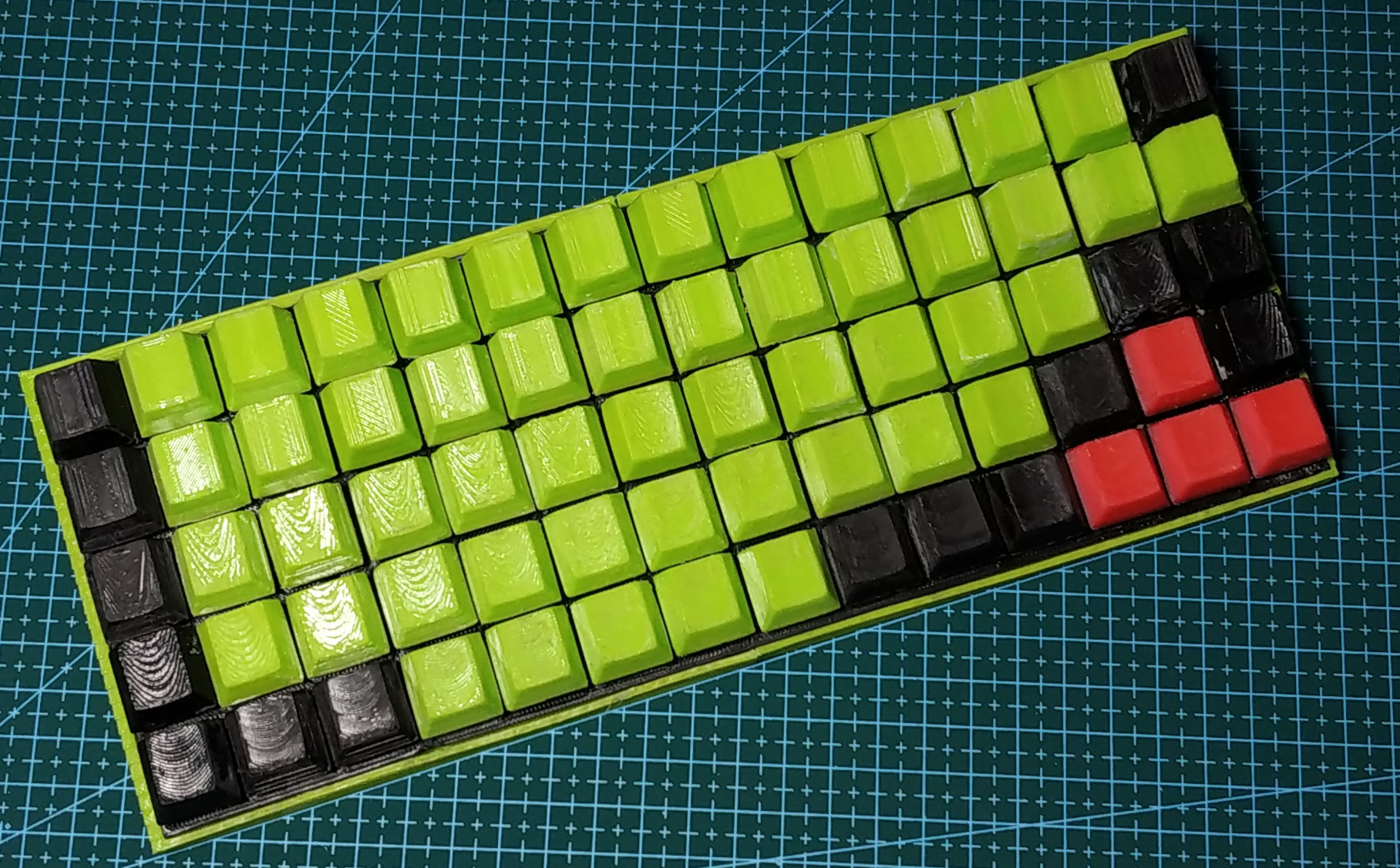
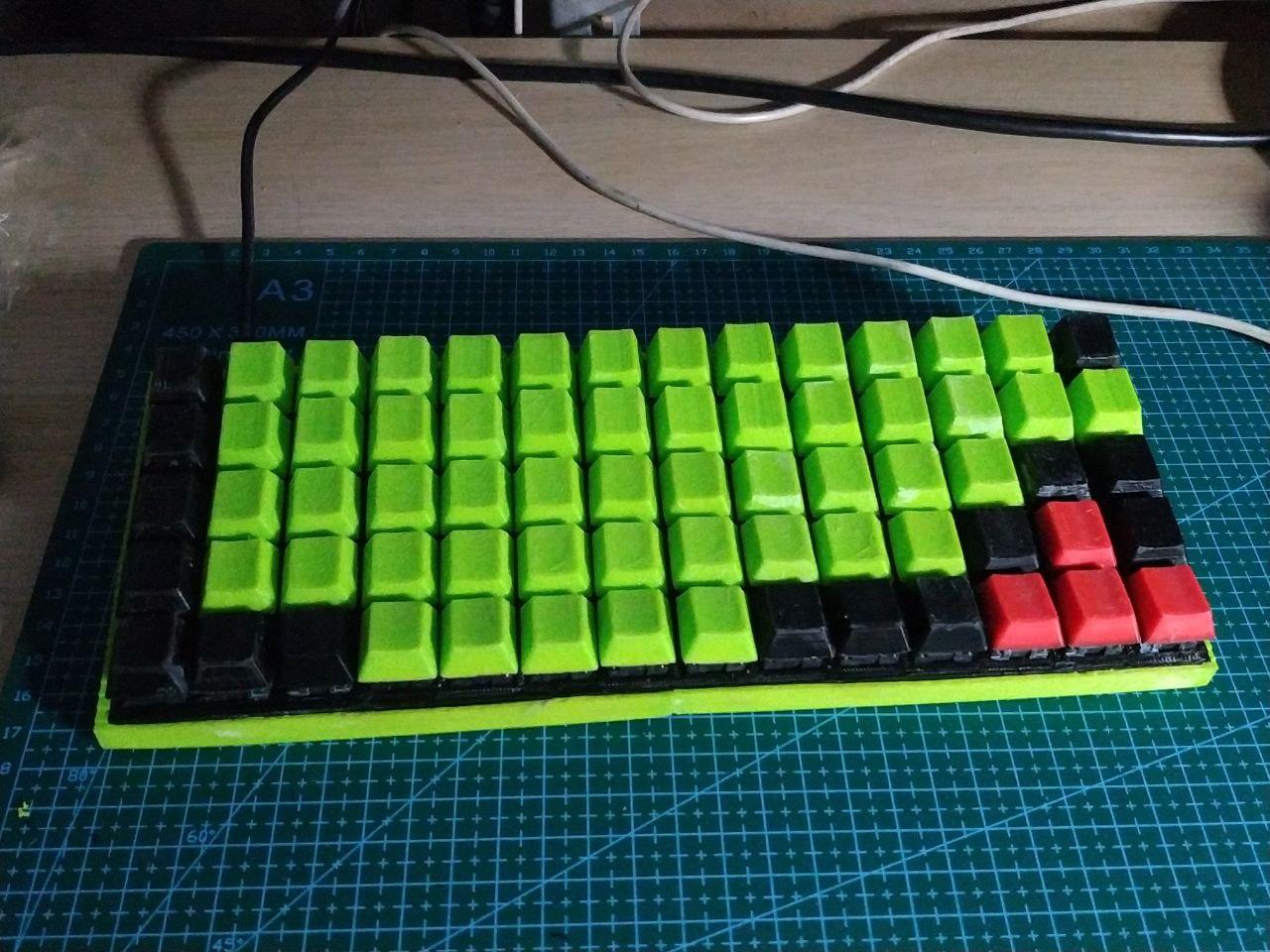 finished CuteBoard, with polished keycaps and all.
The software
For a microcontroller, I chose a Raspberry Pi Pico - just because I already had it. My other choices were a Pi Zero W (cool, but mine was broken enough not to want to talk to me over UART) and an ESP8266 (cool, but a few pins short).
Pi Pico is very user-friendly for the price point and for how well it works - the official docs are a bit convoluted, but all you need to do if you want to just code in micropython/circuitpython is:
- Mount the mass storage device the Pico creates
- Copy over the native python binary, downloaded from their GH Releases page/li>
- Reboot the pico
- `screen /dev/ttyACM0 115200` to get a python REPL
CuteBoard uses the KMK library for reading the keyboard matrix. I was planning to write something of my own that would handle this task, but I don't have enough time to reinvent the wheel. The python file with my layout is available in the project repository, along the rest of the project files.
video of me typing (13MB, 1920x1080 webm [vp9 + opus])What I learned
- It's not actually any hard to build a keyboard from scratch, especially if you have the right parts and tools for the job.
- Old switches tend to be unreliable and work differently depending on how much they've been used. While repurposing them, make sure to take the least used ones (numpad, function keys) and place them in the most commonly used spots (backspace, return, space, arrow keys, letters)
- Trans and nyan-binary rights
- Check twice, assemble once
- Be nice to each other
- If you can, buy some cool keycaps on a********s instead of printing your own. Making keycaps was the most tedious part of the project.
Resources
- project repository
- a blogpost on how the keyboard matrix works
- kmk library
- keyv2 library
- circuitpython binaries for the pico
This post was written entirely on a CuteBoard. (surprisingly - yes, it still works).
Big thanks to Mae for proofreading this blogpost <3

Comments:
Wowwwww, its great work! I will review the codes as soon as possible.
walley at 01.02.2022, 10:57:36looks so nice
Gobol at 17.02.2022, 12:19:25Looks really cool. Can it process multiple keystrokes simultaneously?
nyanpasu64 at 23.02.2022, 05:38:15I don't know much about mechanical keyboards, but: - I'd make the vertical spikes wider on the bottom (possibly 3-4 ribs instead of an entire big circle) to act as bracing and eliminate the stress concentration where the spikes meet the bottom board. - Non planar slicing might allow smooth keycaps with a filament-based 3D printer.
qiu at 24.10.2022, 17:09:33didn't expect the key caps to be 3d printed. Love the layout!
By commenting, you agree for the session cookie to be stored on your device ;p